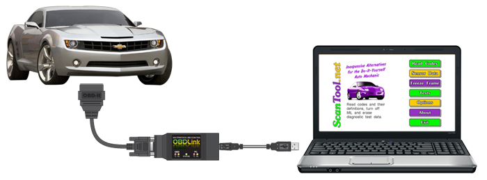
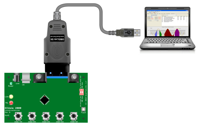
Engineers and programmers are often intimidated by the prospect of interfacing with OBD-II systems. Five protocols, a dozen modes, hundreds of parameters, thousands of trouble codes. Who can figure it all out? The good news is, tapping into the wealth of information available on the OBD bus is easier than you think. To get started, you will need three things: documentation, an OBD interface, and an ECU or a simulator.
Documentation
- SAE J1979 specifies diagnostic services and functionally addressed request/response messages. In a nutshell, it describes how to format requests for information (coolant temperature, VIN, trouble codes) and how to interpret the responses. This standard is available for purchase from SAE, although some of the information is available for free on Wikipedia.
- STN1100 Family Reference and Programming Manual describes the features and command set of the STN1100 family of OBD interpreter ICs.
- ELM327 datasheet provides an overview of the ELM327 command set emulated by the STN11xx ICs.
OBD Interface
The articles in this series assume that you are using an STN11xx-based OBD interface (OBDLink, microOBD, STN1110), although many of the examples will work with the older ELM327-based interfaces as well. An OBD interface, sometimes referred to as “OBD adapter”, is an digital device whose job is to convert OBD signals that the host system can understand, like UART or RS-232. A useful analogy is to think of the OBD interface as a modem.

ECU or ECU Simulator
In order to test your software, you will need to connect the interface to an OBD-compliant vehicle, a benchtop ECU, or an ECU simulator (highly recommended).

